TR-4 Engine Build (Spring 2009)
Triumph TR-4 Engine Build Spring 2009
Disassembly Engine Build Engine installation
(click on any of the thumbnail pictures below for larger pictures, "back" to return)
This assembly goes along with the "engine building tips".
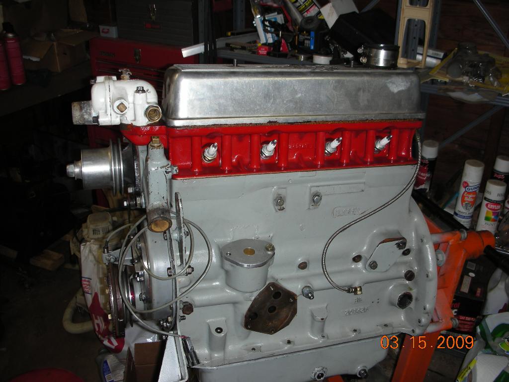
Start of assembly - bare, clean block

Press in main bearings, coat liberally with Redline assembly lube.

My crankshaft's sealing surface is a little undersized (arrggghhh!). I'm carefully trimming the split seal a little and shortening the spring from 8-1/4" to 8" in hopes that maybe my rear main won't leak like a sieve


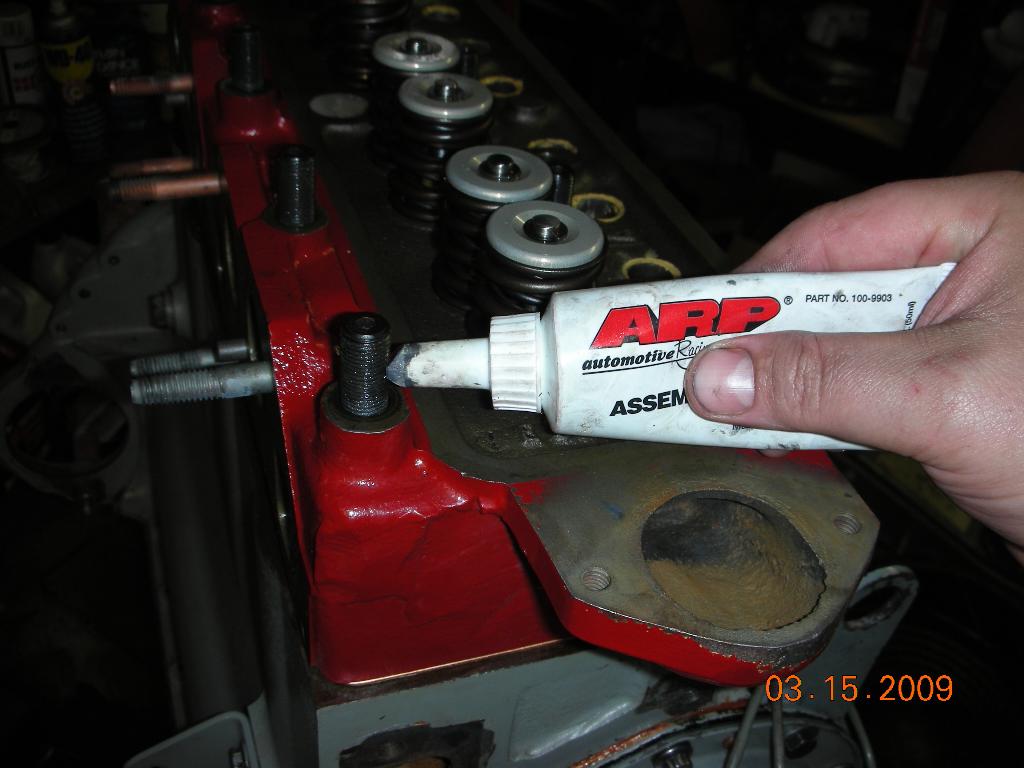
Here are most of the sealants I'll use. Edelbrock Gasgacinch for the head gasket, Permatex Indian Head, and Permatex Ultra Black. I also use Permatex Ultra Copper on a couple of parts - the front plate to block and water pump to block. Redline Assembly Lubricant is used on most of the moving surfaces and ARP Assembly Lubricant is used on all of the ARP bolts and studs.

Rear main - put a small amount of ultra black on the seal surface, redline assembly lube on the bearing. Main cap side I do the same, of course.

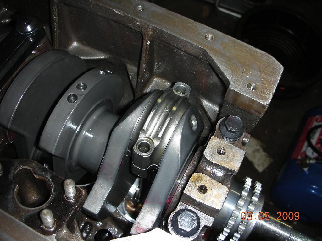
Lay the crank in the bearings in the block, then lube the ARP main bolts with ARP Assembly Lubricant, and torque to 90 ft lbs in stages (40 then 75 then 90). Split of split seal is pointing up when engine is upright (down in this upside down arrangement). I sure hope it seals this time.


If you forget the orientation of the center main, the bearing notch is on the same side for block and cap. It's extremely important to not install it backwards.
I don't show the thrust washer installation - coat liberally with Redline assembly lube, MAKE SURE SLOTTED SIDE FACES CRANK, verify that crank end thrust is around 0.005" - put a dial indicator on the end of the crank and push forcefully each way. In my case, I needed a pair of normal thickness thrust washers and a pair of 0.005" thicker thrust washers. Crank made slightly imperfectly...
After torquing main caps, verify that the crank still turns freely. Here you see me turn it by hand.


I don't show the installation of the front main aluminum block. Check the uncle jack's engine building tips for further details on that one. I trimmed the cork gasket to fit the block and mashed it in place.
Piston rings (of course the liners have been honed, no pictures of that) - verify piston ring gap by putting in a liner and pushing down with a piston (so it's flat with the liner) and measure the end gap with a feeler gauge. Top ring gap for 87mm liner should be 0.014", 2nd ring gap should be 0.011". If gap is too small, file the end of the ring. There are tools to do this more quickly and evenly. I do this "old school" with a hand file, and the ends are not totally flat - I check often and correct the angle of the file so the ends are pretty good.


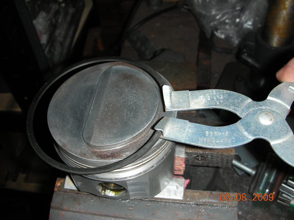
Carefully install rings on piston, making sure end gaps don't line up. I've got the oil ring bottom 90 degrees from the wrist pin (top oil ring is rotated 180 degrees from the bottom one), the 2nd ring is pointing to one wrist pin hole, and the top ring is pointing to the other wrist pin hole. Use piston ring compressor and carefully tap into liner with handle end of a hammer. Be sure that the connecting rod doesn't hit the crank journal - guide the end with your hand if you can.


I install the pistons one at a time and assemble the rod cap to the rod, using assembly lube, of course. I install the bearing into the rod after piston installation. By the way, my bearings are ceramic coated by Calico Coatings - http://www.calicocoatings.com/bearings.html . After the last disassembly, I'm sold on this technology! Rod bearing caps are matched to the rod, but if you lose the orientation, the "notch" is on the same side on the rod and the cap. Same with the main bearing caps. My Carillo rods have "CARR" bolts - using ARP assembly lube, they should be torqued to 65 ft lbs. A stretch gauge is more accurate, though. Verify free movement of crank after the installation of each rod.


Rear main seal has "felt" that seals it against the block. The felt that came with the Payen kit was too small (arrgghh!), but the extra felt I bought from Moss was large enough. Dip it in Indian Head and mash it into the hole. Messy job. I don't show me hammering the felt home with a Phillips screwdriver. Really mash it in there, and trim it flush with the pan gasket surface. I left one side a little proud of the surface hoping that the pan would keep the felt slightly under compression.


Trim the front plate gasket so the holes match the block. I use Ultra Copper on both sides of this gasket - the Indian Head I used last year leaked.


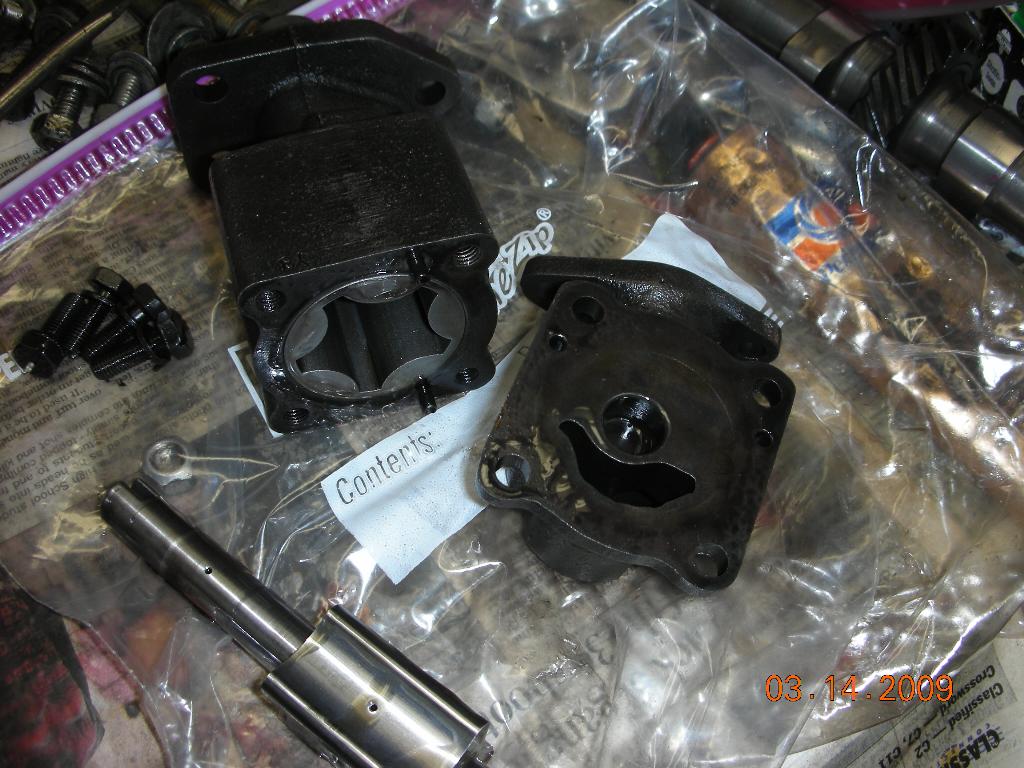
Steve Yott's uprated oil pump (contact Steve here: tr4@wi.rr.com ) Fixes a couple of failure modes of stock pump. Rotor is supported on BOTH ends, reducing flex and commensurate stress on the shaft. Rotor is not a separate part, it's integral with the shaft. There are oil galleries so that none of it will be metal to metal once it's spinning. Very cool.


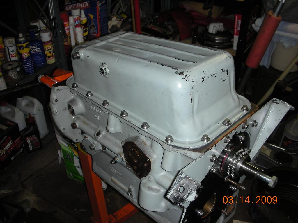
Detail of pan baffle and oil temp sensor fitting


Ultra Black on both sides of pan gasket, install pan.

Camshaft installation - lubricate lobes with stiff cam lube (from a cam manufacturer), the journals with Redline assy lube. Use long bolts in the front to assist in installation so that the bearings don't get beat up in the installation.


Now we come to "degreeing the cam". I put a degree wheel on the front of the crank, and use a dial indicator to set the top dead center (TDC) mark accurately.


Now, install the lifter for the #1 intake (2nd hole from the front!), and since my cam spec is at 0.050" of lift, I rotate the cam to that setting. I rotate the crank to the the setting on my cam sheet (in this case, 21.5 degrees before top dead center - BTDC).


With the cam and crank at the proper orientation, play with the timing chain / cam sprocket to see if I can get the bolt holes to line up. Then, use blue locktite on the cam bolts and torque them down.


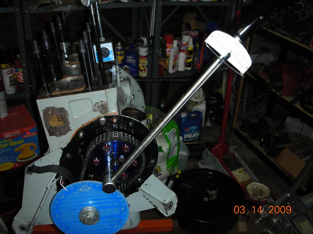
You can see the sheet where I figure the lift under the lifter. I was 3 degrees off with the initial install, and used my vernier cam sprocket to allow some adjustment - loosened the set screws, rotated the crank 3 degrees, tightened it down and verified that the setting was correct. Lube the lifters with cam lube on the foot, assembly lube on the sides. These are the super trick ceramic lifters that are no longer being made.

Front cover installed - I used Ultra Black on the gasket.

Detail of the head.


Head gasket and head installation. Mark head so I know where the gasket will be. Coat head, block and both sides of head gasket with Gasgacinch. Let dry for at least 5 minutes. Assemble, lubing ARP head studs with ARP assy lube and torquing in stages up to 100 ft lbs.


Use jam nuts to install the valve cover studs. The rocker studs are ARP - available from Ken Gillanders at British Frame and Engine. Totally eliminated my problem breaking the rearmost rocker stud.


My engine came with valve caps, and I like them to allow a bit more misalignment of the rocker assembly without harm. The also protect the valve stems from mushrooming. They are a standard "speed part", but I had to cut them down with my bench grinder so they didn't hit the valve keepers.


Attaching the rocker assembly. With the ARP studs I can torque to 40 ft lbs.


Adjust valves.

Attach water pump, thermostat housing, valve cover, external rocker arm oil feed, and in my case, oil pump shaft. There's a bit more messing about with a proper distributor.